Goal
Plan the layout for circuit board and wire layout for the left and right hand of the accordion.
The Problem
Making everything connect can be fairly straightforward, but designing the best way to do it is an art form in itself. Once you have a final draft of how you want to map the circuit boards it’ll be time to solder everything onto them.
Disclaimer: The accordion is not a standardized instrument - they vary greatly in how they are manufactured, so the inner workings can be different from accordion to accordion. That being said, take this guide with a grain of salt, as not all of these instructions may exactly apply to your model of accordion. Also, this guide assumes you’ve chosen in the previous guide to attach blockers on the inside of the accordion (unless otherwise specified).
Solution
1. Determining component layout
Let’s start by running down the list of what components we need for our circuit and where in the accordion they need to go:
- 24 opto-interruptors on the bass (left-hand) side
- Includes 3 transistors
- 41 opto-interruptors on the treble (right-hand) side
- Includes 5 transistors
- ArduinoMega
- Can be placed wherever it best fits. I chose the treble side facing the bellows
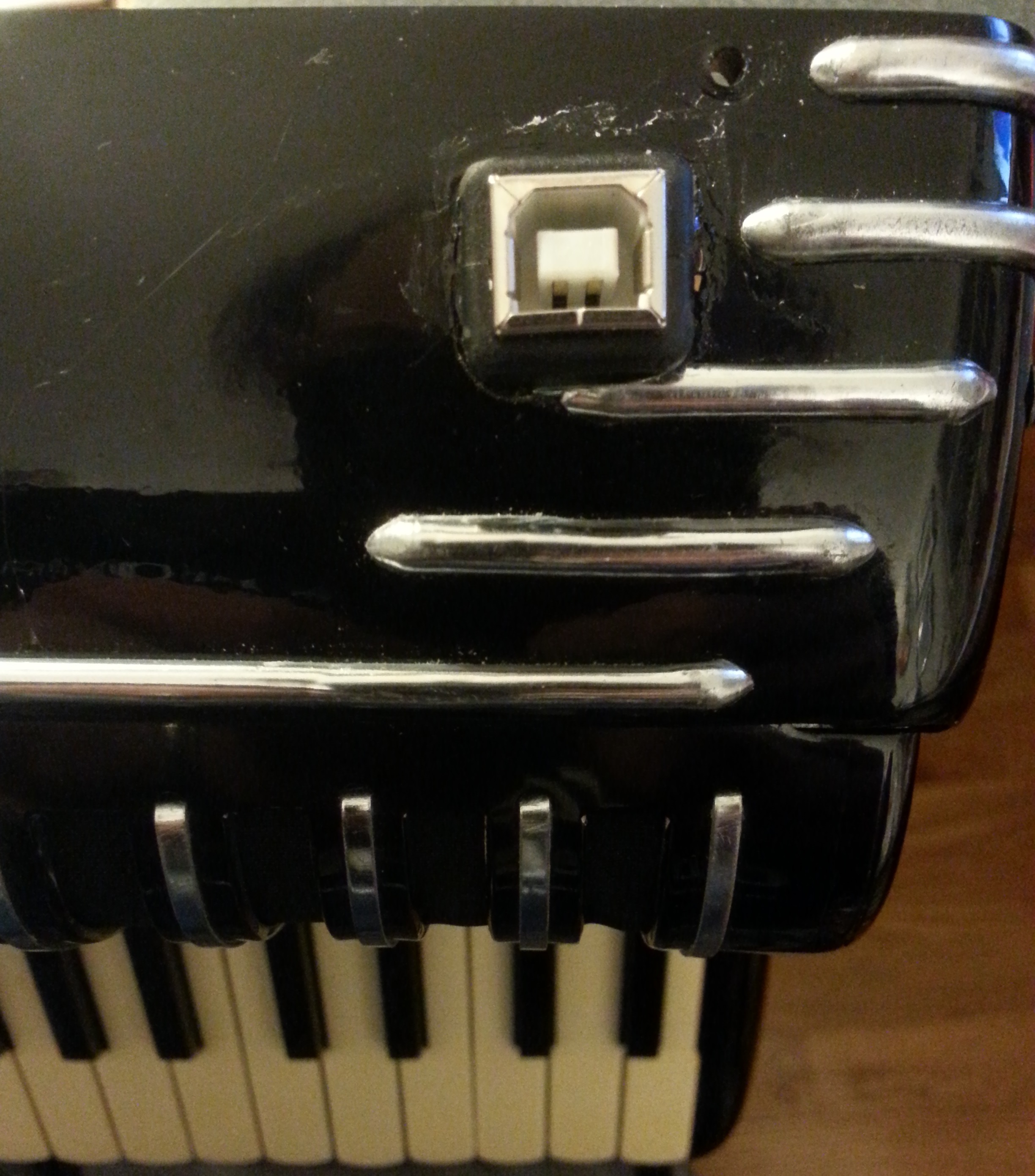
- USB Port (to allow plugging in the instrument to the computer for power and/or software updates)
- Should be placed relatively near the Arduino in a location where it’s not uncomfortable to play the instrument while being plugged in. I chose the bottom of the treble side.
- (Optional) HC-05 Bluetooth Transceiver
- Can be placed wherever it best fits. I chose the treble side on a separate board with a 3.3V power rail.
- (Optional) BMP180 Barometric Pressure Sensor
- Can be placed wherever it best fits. I chose the treble side on the same board as the HC-05.
- Room for more
- You never know when you might want to add something new down the line (like extra MIDI controls or other bells and whistles), so it’s always a good idea to leave some room for expansion if you can spare it.
From here you need to decide where all of these components are going to live. Consider the following:
- How will you mount the opto-interruptors?
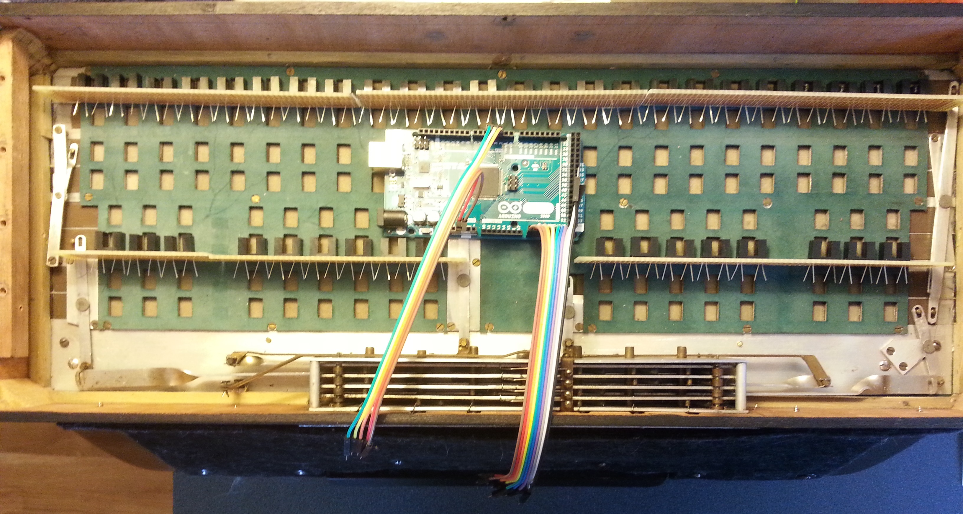
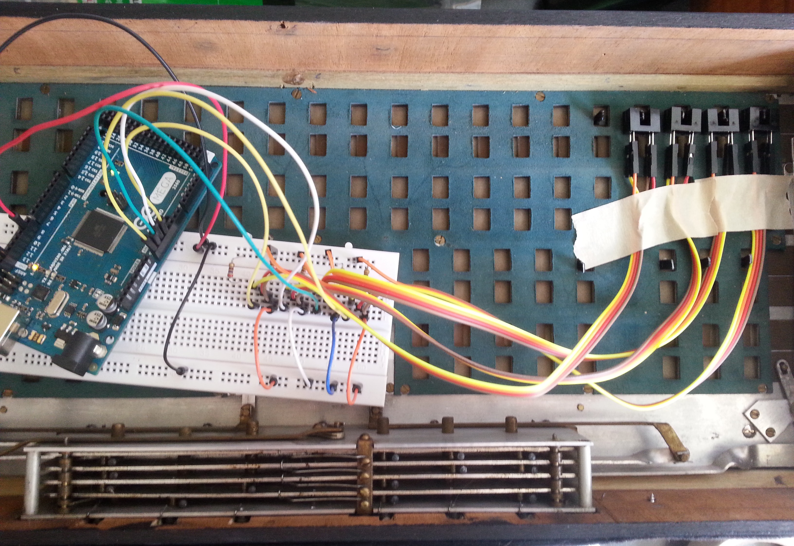
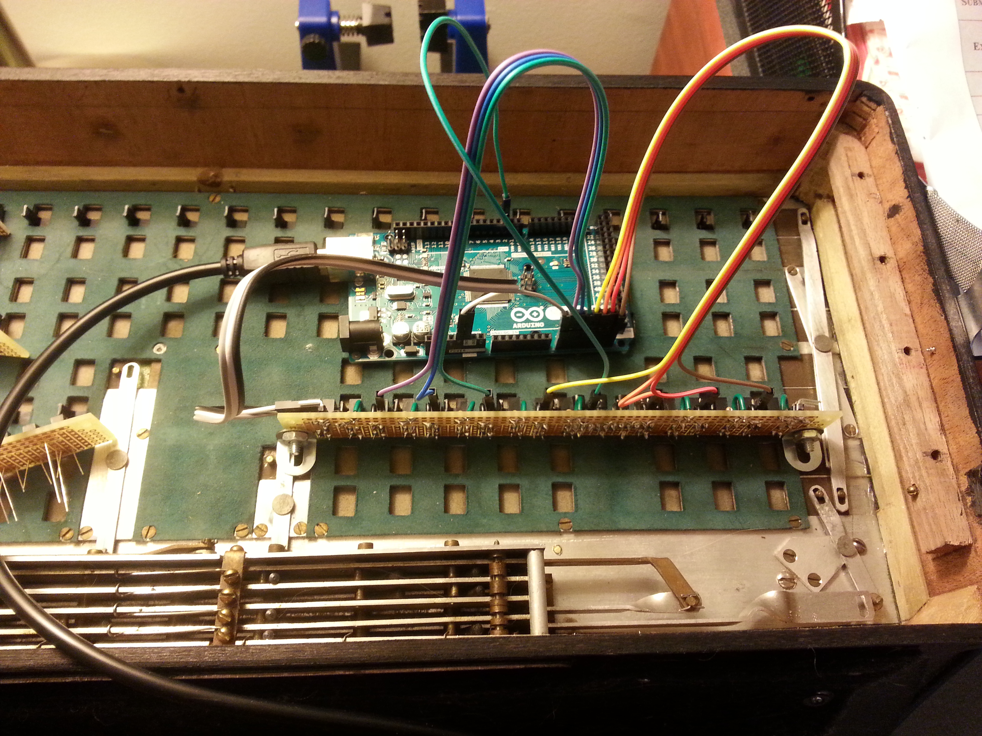
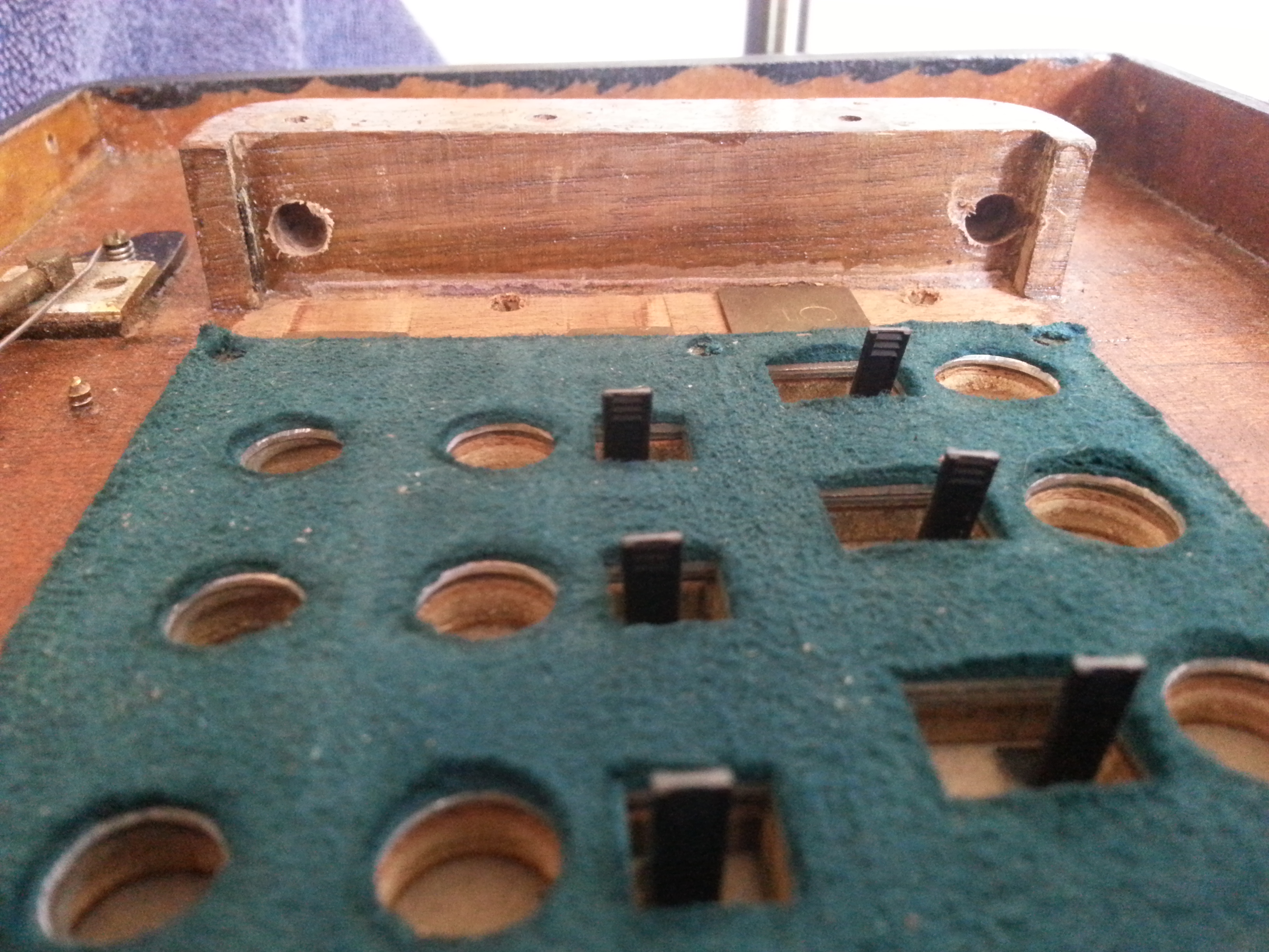
- There are two main choices - either you can glue them in place and wire them together, or you can solder them straight onto a PCB and mount that instead. The choice may depend on your accordion’s layout and how you chose for the opto-interruptors to react to key presses. Wiring the interruptors would be more flexible, but it would also be more labor intensive. I chose to solder them to PCBs that I mounted vertically to angle brackets that I glued to the surface of the bellows.
- How will you mount the other components?
- The PCB boards will likely either need to be drilled into a wooden surface or glued onto a wooden or metal surface. If drilling, take note of where you’d be drilling into so as not to damage the inner workings of the accordion.
- How will you connect the left hand side to the right hand side?
- No matter where you put the Arduino or any of the other components, you are going to have at least 13 wires travelling from the left hand side across the bellows to the right hand side: 8 analog pins, 3 (or 6) digital pins, 5V, and GND. You will need to determine how long those wires need to be to allow for extending the bellows as far as they will go when playing, and they should be positioned such that they will not get in the way of closing the bellows.
- Note: If you chose to skip adding the BMP this isn’t as much of an issue - you could just keep the wires on the shorter side and just keep the bellows closed at all times.
- No matter where you put the Arduino or any of the other components, you are going to have at least 13 wires travelling from the left hand side across the bellows to the right hand side: 8 analog pins, 3 (or 6) digital pins, 5V, and GND. You will need to determine how long those wires need to be to allow for extending the bellows as far as they will go when playing, and they should be positioned such that they will not get in the way of closing the bellows.
2. Drafting the Component PCB(s)
There are many ways to connect the opto-interruptors together, and it’s important to have a solid draft of your final plan to follow. I went through about 6 different drafts before I finally settled on the one I wanted to build. Some things to take into consideration:
- Soldering to PCB vs Wiring
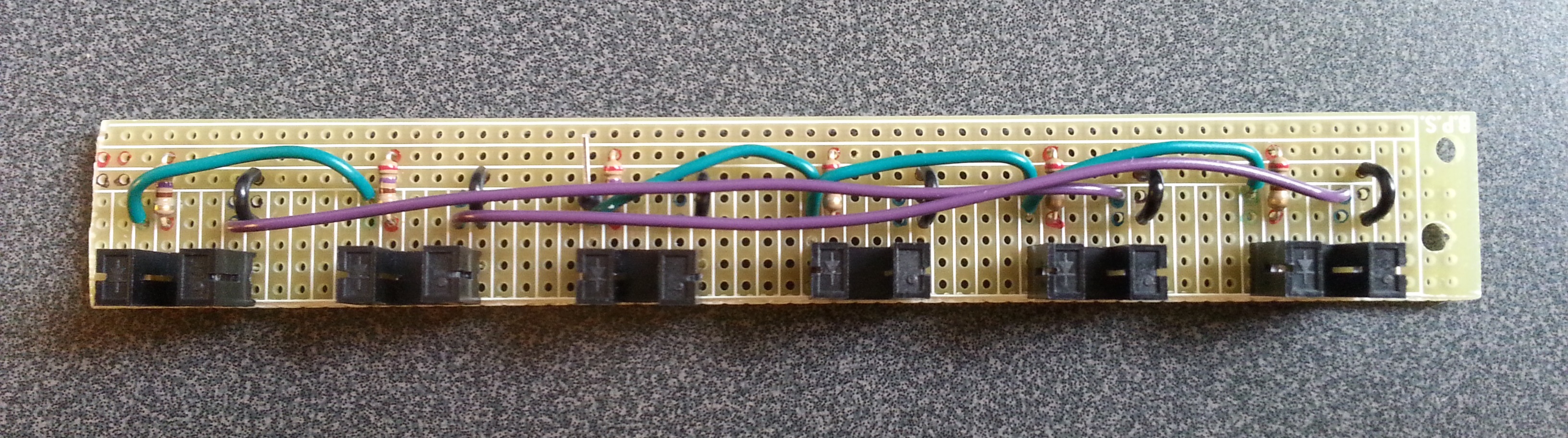
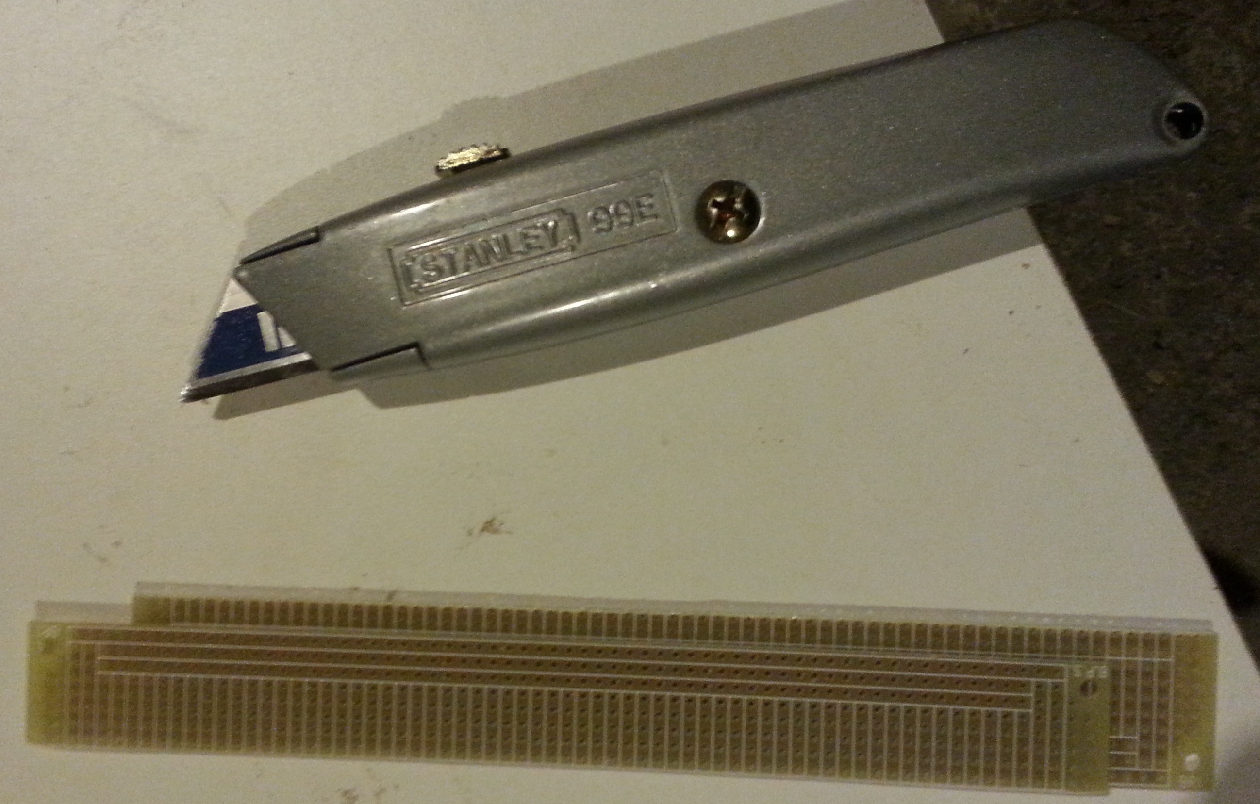
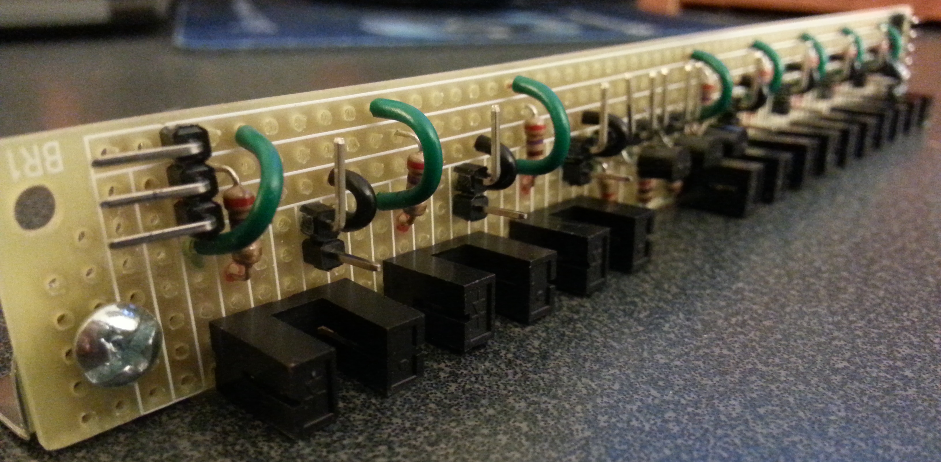
- My first draft involved wiring all the optos together and soldering the wires to a single PCB at the end of the accordion. Then I realized I could solder them directly onto a board if I cut the board the right way. This saves me a TON of wiring in place of soldering. The downside to this approach is I no longer have the flexibility to tweak the positioning of an individual sensor if needed (e.g. if the blocker was glued in the wrong place). Also, I had to figure out how to properly mount the PCBs vertically. If you decide wiring is right for you, you can chain all emitter pins together since they all go to GND.
- Grouping the opto-interruptors by analog pin vs by digital pin
- No two interruptors will have the same two analog and digital pins, so you’ll have to group by one or the other. I chose to group them by digital pin because all 8 interruptor diodes can be connected to the same transistor. (maybe insert image?) This is especially useful if you decide to go with the wiring option since you can chain all the cathode pins of the same digital pin together before wiring it to the collector of the transistor.
Once you think you have a solid plan, it’s time to turn it into action!